
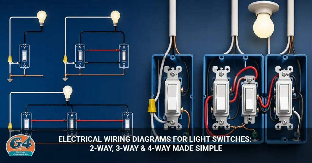
Electrical wiring diagrams for light switches show how wires connect to switches and light fixtures to control lighting from one or more locations. A 2-way switch controls a light from one location, a 3-way switch controls it from two locations, and a 4-way switch allows control from three or more locations.
Understanding these wiring diagrams helps you identify wires, troubleshoot switch problems, and understand how lighting circuits work. Whether you’re replacing a switch, planning a renovation, or trying to understand an existing electrical setup, knowing the difference between 2-way, 3-way, and 4-way switch wiring can save time and prevent mistakes.
In this guide, you’ll learn how each switch configuration works, what the wiring diagrams mean, where each setup is commonly used, and the most common wiring problems homeowners encounter.
Understanding Light Switch Wiring Basics
Understanding light switch wiring basics helps you read wiring diagrams more easily and troubleshoot common switch problems. Most light switch circuits use a few key wires that work together to deliver power safely to a light fixture.
Before working with any wiring diagram, it’s important to know what each wire does and how electricity moves through the circuit. This foundation makes it much easier to understand 2-way, 3-way, and 4-way switch configurations.
How a Light Switch Controls Electricity
A light switch controls electricity by opening or closing an electrical circuit. When you turn the switch on, it completes the circuit and allows electricity to flow to the light fixture. When you turn the switch off, it breaks the circuit and stops the flow of electricity, causing the light to turn off.
Most residential light switch circuits include four main components:
- Hot wire (line): Carries electricity from the electrical panel to the switch.
- Load wire: Carries electricity from the switch to the light fixture.
- Neutral wire: Provides a return path for electricity back to the electrical panel.
- Ground wire: Helps protect against electrical shock by safely directing fault current to the ground.
Each wire has a specific job within the circuit. Understanding their functions can help you identify connections correctly and read wiring diagrams with greater confidence.
Common Wire Colors and Their Functions
Wire colors help identify the purpose of each conductor in a lighting circuit. While electrical wiring colors can vary based on local codes, installation practices, and the age of the home, most residential wiring follows standard color conventions.
The table below shows the most common wire colors used in light switch circuits:
| Wire Color | Typical Function |
| Black | Hot or line wire that carries power from the electrical panel |
| Red | Traveler wire or switched hot wire in multi-switch circuits |
| White | Neutral wire that returns current to the electrical panel |
| Green or Bare Copper | Ground wire that provides protection against electrical faults |
The black wire is typically the wire that delivers power to the switch. Red wires are often found in 3-way and 4-way switch setups, where they act as traveler wires or switched conductors. White wires usually serve as neutral wires, while green or bare copper wires are used for grounding and safety.
Never assume a wire’s function based solely on its color. Wiring may have been modified over time, and older homes may not follow current color standards. Always turn off power and use a voltage tester to verify wire functions before making any electrical connections.
Essential Tools for Light Switch Wiring
Using the right tools makes light switch wiring safer, easier, and more accurate. Whether you’re replacing a switch or troubleshooting a wiring issue, having a few basic electrical tools on hand can help you complete the job properly.
Here are the essential tools commonly used for light switch wiring:
- Non-contact voltage tester: Checks for the presence of electricity without touching exposed wires. This is one of the most important safety tools.
- Screwdrivers: Used to remove switch cover plates, loosen terminal screws, and install new switches.
- Wire strippers: Remove insulation from wires without damaging the conductors.
- Needle-nose pliers: Help bend, grip, and position wires in tight electrical boxes.
- Electrical tape: Provides additional insulation and helps secure wire connections when needed.
- Wire connectors: Join wires together safely and securely inside electrical boxes.
- Flashlight or work light: Improves visibility when working in dimly lit areas or after shutting off power to the circuit.
Before starting any electrical work, make sure your tools are in good condition and rated for electrical use. Using the proper tools not only improves installation quality but also reduces the risk of electrical shock and wiring mistakes.
Safety Tips Before Working on Wiring
Safety should always come first when working on any electrical wiring. Even a simple light switch replacement can become dangerous if power is not properly disconnected or wiring is handled incorrectly.
Before touching any wires, follow these essential safety steps:
- Turn off power at the breaker panel. Locate the correct circuit breaker and switch it off before starting any work.
- Confirm the power is off. Use a non-contact voltage tester to verify that no electricity is present at the switch, wires, or electrical box.
- Use insulated tools. Electrical-rated tools provide an extra layer of protection when working around wiring.
- Keep your work area dry. Never perform electrical work in wet conditions or with wet hands.
- Follow local electrical codes. Building and electrical codes help ensure safe installations and may vary by location.
- Inspect wiring before making connections. Look for damaged insulation, loose wires, signs of overheating, or corrosion.
- Call a licensed electrician when necessary. If you are unsure about the wiring configuration or encounter unexpected issues, professional assistance is the safest option.
Taking a few extra minutes to follow proper safety procedures can help prevent electrical shocks, equipment damage, and potential fire hazards. When working with electricity, it’s always better to be cautious than to take unnecessary risks.
What Is a 2-Way Light Switch?
A 2-way light switch controls a light fixture from a single location. It is the most common type of light switch used in residential buildings and is ideal for rooms where only one switch is needed to operate the lights.
When you flip the switch on, it completes the electrical circuit and allows power to reach the light fixture. When you turn it off, the circuit is broken, and the light goes out. Because of its simple design, a 2-way switch is often the easiest switch configuration to install, replace, and troubleshoot.
Most homeowners encounter 2-way switches throughout their homes because they work well in spaces that have only one entrance or where controlling a light from multiple locations is unnecessary.
Common Applications for 2-Way Switches
2-way switches are typically used in rooms where a single switch can conveniently control the lighting. They are simple, reliable, and suitable for most standard lighting circuits.
Common locations include:
- Bedrooms
- Bathrooms
- Closets
- Utility rooms
- Laundry rooms
- Pantries
- Small offices
- Storage rooms
In these spaces, users generally enter and exit through the same area, making a single switch location practical and efficient.
Because of their straightforward operation and lower wiring complexity, 2-way switches remain the most widely installed light switches in homes and small commercial buildings.
How a 2-Way Switch Works
A 2-way switch works by either completing or breaking the electrical circuit that powers a light fixture. When the switch is turned on, electricity flows through the switch to the light, allowing it to illuminate. When the switch is turned off, the circuit is interrupted, stopping the flow of electricity and turning the light off.
In a typical 2-way switch circuit, power enters the switch through the hot (line) wire. The switch then controls whether that power continues to the load wire connected to the light fixture.
The process works as follows:
- Electricity travels from the electrical panel to the switch through the hot wire.
- When the switch is turned on, the internal contacts close and complete the circuit.
- Power flows from the switch to the light fixture through the load wire.
- The light turns on.
- When the switch is turned off, the contacts open and break the circuit.
- Power can no longer reach the light fixture, causing the light to turn off.
Because a 2-way switch controls a light from only one location, its wiring is relatively simple compared to 3-way and 4-way switch configurations. This simplicity makes it one of the most common and easiest lighting circuits to understand.
Components of a 2-Way Switch Circuit
A standard 2-way switch circuit consists of five main components that work together to control a light fixture from a single location. Each component has a specific role in delivering power safely and allowing the switch to turn the light on and off.
The key components include:
- Incoming power source: Supplies electricity from the electrical panel to the circuit.
- Single switch: Controls the flow of electricity to the light fixture by opening or closing the circuit.
- Light fixture: Receives power from the switch and produces light.
- Neutral connection: Provides a return path for electrical current back to the electrical panel.
- Ground connection: Helps protect against electrical faults and reduces the risk of electric shock.
In a typical setup, electricity travels from the power source to the switch. When the switch is turned on, power continues to the light fixture. The neutral wire completes the circuit, while the ground wire provides an important safety layer.
Understanding these components makes it easier to read wiring diagrams, identify wires correctly, and troubleshoot common switch and lighting issues.
Basic 2-Way Light Switch Wiring Diagram
A basic 2-way light switch wiring diagram shows a single switch controlling a light fixture from one location. In this setup, electricity flows from the power source to the switch and then to the light fixture when the switch is turned on.
The wiring path typically follows:
Power Source → Switch → Light Fixture
The switch acts as a gate within the circuit. When the switch is turned on, it closes the circuit and allows electricity to flow to the light. When the switch is turned off, it opens the circuit and stops the flow of electricity, turning the light off.
A standard 2-way switch circuit usually includes:
- Power source (electrical panel)
- Hot (line) wire
- Single-pole switch
- Load wire
- Light fixture
- Neutral wire
- Ground wire
Although the wiring layout is relatively simple, every connection must be made correctly to ensure safe and reliable operation. The hot wire delivers power to the switch, the load wire carries power to the light fixture, the neutral wire completes the circuit, and the ground wire provides protection against electrical faults.
Because of its straightforward design, the 2-way switch wiring diagram is often the first circuit homeowners and DIYers learn when studying residential electrical systems.
Common 2-Way Wiring Mistakes
Incorrect wiring can cause a 2-way light switch to malfunction and may create serious safety risks. Many switch problems are caused by a few common installation mistakes that can often be avoided with careful wiring and proper safety checks.
Some of the most common 2-way wiring mistakes include:
- Loose terminal connections: Wires that are not securely attached to switch terminals can cause flickering lights, intermittent operation, or overheating.
- Incorrect grounding: Failing to connect the ground wire properly can increase the risk of electrical shock and reduce circuit safety.
- Reversed line and load wires: Connecting the incoming power wire and the wire leading to the light fixture incorrectly can cause the switch to operate improperly.
- Damaged wire insulation: Cuts, cracks, or worn insulation can expose conductors and increase the risk of short circuits and electrical faults.
- Overfilled electrical boxes: Placing too many wires inside a small electrical box can lead to overcrowding, damaged insulation, and excessive heat buildup.
Other mistakes include using the wrong wire size, failing to tighten wire connectors properly, or neglecting to test the circuit before restoring power.
To avoid these issues, always turn off power at the breaker, verify connections against the wiring diagram, and inspect all wires for damage before completing the installation. Taking the time to wire the switch correctly helps ensure safe, reliable operation and reduces the likelihood of future electrical problems.
What Is a 3-Way Light Switch?
A 3-way light switch allows you to control the same light fixture from two different locations. Unlike a standard 2-way switch, which controls a light from a single location, a 3-way switch setup provides greater convenience by letting you turn the light on or off from either switch.
This type of wiring configuration uses two 3-way switches connected by traveler wires. The switches work together to control the flow of electricity to the light fixture, regardless of which switch is used.
3-way switches are commonly installed in areas where people enter and exit from different locations. They improve convenience, safety, and accessibility by eliminating the need to walk through a dark space to reach a switch.
Common Locations for 3-Way Switches
3-way switches are most useful in spaces that have multiple entry or exit points. They allow users to control lighting from either end of an area, making everyday movement through the home more convenient.
Common locations include:
- Hallways
- Staircases
- Garages
- Large living rooms
- Long corridors
- Basements
- Open-concept spaces
- Large bedrooms with multiple entrances
For example, a hallway may have one switch near the front entrance and another at the opposite end. A staircase often has one switch at the bottom and another at the top. In both cases, the light can be controlled from either location, improving safety and convenience.
Because of their practical benefits, 3-way switches are one of the most common multi-location lighting control systems found in residential properties.
How a 3-Way Switch Works
A 3-way switch works by allowing two separate switches to control the same light fixture. Unlike a standard switch, a 3-way switch does not have fixed ON and OFF positions. Instead, the light’s status depends on the position of both switches in the circuit.
The system uses two 3-way switches connected by traveler wires. When either switch is flipped, the electrical path changes, either completing or interrupting the circuit. As a result, the light can be turned on or off from either location.
This setup is ideal for areas where controlling a light from two different points improves convenience and safety, such as hallways and staircases.
Understanding 3-Way Switch Terminals
A 3-way switch contains three active terminals and one ground terminal. Each terminal serves a specific purpose within the circuit.
The terminals include:
- Common terminal: Connects to either the incoming power source or the wire leading to the light fixture.
- Traveler terminal 1: Carries electrical current between the two switches.
- Traveler terminal 2: Provides an alternate path for current between the switches.
- Ground terminal: Connects the switch to the grounding system for safety.
The common terminal is usually identified by a darker-colored screw, often black, while the traveler terminals typically use brass-colored screws. Correctly identifying these terminals is essential when installing or replacing a 3-way switch.
Basic 3-Way Wiring Diagram Structure
A basic 3-way wiring diagram shows how two switches work together to control a single light fixture from different locations.
The wiring path generally follows:
Power Source → First 3-Way Switch → Traveler Wires → Second 3-Way Switch → Light Fixture
In this configuration:
- Power enters the first 3-way switch.
- Traveler wires connect the two switches.
- The second switch directs power to the light fixture.
- The neutral wire completes the circuit.
- The ground wire provides electrical safety.
The traveler wires are the key difference between a standard switch circuit and a 3-way switch circuit. They create multiple electrical paths, allowing either switch to change the state of the light independently.
Understanding this wiring structure makes it much easier to read 3-way switch diagrams and troubleshoot common wiring issues.
Common 3-Way Switch Problems
Most 3-way switch problems are caused by incorrect wiring, loose connections, or improperly identified terminals. Because a 3-way circuit is more complex than a standard switch setup, even a small wiring mistake can prevent the switches from working correctly.
Some of the most common 3-way switch issues include:
- Light only works from one switch: This often occurs when traveler wires are connected incorrectly or one of the switches is wired to the wrong terminal.
- Light remains constantly on: A miswired common terminal or faulty switch can cause the circuit to stay closed continuously.
- Light remains constantly off: This may result from a loose wire connection, a damaged switch, or incorrect traveler wire placement.
- Misidentified traveler wires: Connecting traveler wires to the common terminal is one of the most frequent installation mistakes.
- Loose common wire connections: A loose common wire can cause intermittent operation or prevent the switches from controlling the light properly.
Other possible causes include worn switch contacts, damaged wiring, loose wire connectors, or connections that were not tightened securely during installation.
When troubleshooting a 3-way switch circuit, start by turning off power at the breaker panel and inspecting each connection against the wiring diagram. Carefully verify the common terminal, traveler wires, and ground connections. In many cases, correcting a misplaced wire restores normal operation.
If the wiring appears correct but the problem continues, one of the switches may be defective and require replacement.
What Is a 4-Way Light Switch?
A 4-way light switch allows you to control the same light fixture from three or more locations. It is commonly used in larger spaces where having multiple switch locations makes lighting more convenient and accessible.
Unlike a 2-way switch, which controls a light from one location, or a 3-way switch, which controls it from two locations, a 4-way switch expands the system so additional switches can be added. This makes it possible to turn the light on or off from several points within the same area.
4-way switch systems are often found in large homes, commercial buildings, and spaces with multiple entrances or access points.
When a 4-Way Switch Is Needed
A 4-way switch is needed when a light must be controlled from three or more locations. This setup improves convenience and safety by allowing users to operate the lighting system without walking to a single switch location.
Common applications include:
- Multi-story stairways
- Large hallways
- Open-concept homes
- Conference rooms
- Commercial facilities
- Large basements
- Warehouses
- Buildings with multiple entrances
For example, a long hallway may have switches at both ends and another switch in the middle. A 4-way switch makes this type of multi-location control possible.
How a 4-Way Circuit Operates
A 4-way circuit works by adding a 4-way switch between two 3-way switches. The 4-way switch redirects the traveler wires, creating additional paths for electricity to flow through the circuit.
A typical configuration follows this structure:
3-Way Switch → 4-Way Switch → 3-Way Switch
When any switch in the circuit is operated, the electrical path changes, which either completes or interrupts the circuit and changes the state of the light.
Unlike a 3-way switch, which has a common terminal, a 4-way switch is designed specifically to receive and redirect traveler wires between the two 3-way switches. This allows multiple switches to work together while controlling a single light fixture.
Additional 4-way switches can be installed between the two 3-way switches if more control locations are needed. This flexibility makes 4-way switch systems ideal for large residential and commercial spaces where convenient lighting control is important.
Components of a 4-Way Circuit
A 4-way switch circuit uses multiple switches to control a single light fixture from three or more locations. Understanding the main components of the circuit makes it easier to read wiring diagrams and troubleshoot wiring issues.
A standard 4-way switch setup typically includes:
- Two 3-way switches: Installed at each end of the circuit and used to start and complete the switching system.
- One or more 4-way switches: Installed between the two 3-way switches to provide additional control locations.
- Traveler wires: Connect the switches and carry the switching paths throughout the circuit.
- Light fixture: Receives power when the circuit is completed and provides illumination.
- Ground connections: Protect the circuit and help reduce the risk of electrical shock.
The two 3-way switches serve as the endpoints of the circuit, while the 4-way switch redirects the traveler wires between them. If additional control locations are needed, more 4-way switches can be added between the two 3-way switches.
Common 4-Way Wiring Errors
Most 4-way switch problems occur because of incorrect wiring connections. Since these circuits are more complex than standard switch setups, even a small wiring mistake can prevent the system from functioning properly.
Common 4-way wiring errors include:
- Traveler wires connected incorrectly: Crossing traveler wires or connecting them to the wrong terminals can prevent the switches from working as intended.
- Improper terminal connections: Connecting wires to the wrong screw terminals can interrupt the switching sequence.
- Misidentified switch terminals: Confusing traveler terminals with other terminals is a common installation mistake.
- Loose wiring connections: Loose wires can cause intermittent operation, flickering lights, or complete circuit failure.
Other potential issues include damaged traveler wires, faulty switches, and wiring that does not match the intended circuit diagram.
Because 4-way circuits involve multiple switches and traveler wire connections, labeling wires during installation or replacement can save significant troubleshooting time later. Verifying each connection against the wiring diagram before restoring power helps prevent many common wiring errors.
Comparing 2-Way, 3-Way, and 4-Way Switch Wiring
The main difference between 2-way, 3-way, and 4-way switch wiring is the number of locations from which you can control a light fixture. As the number of control points increases, the wiring becomes more complex and the installation requires additional switches and traveler wire connections.
The table below highlights the key differences between these common light switch configurations:
| Feature | 2-Way Switch | 3-Way Switch | 4-Way Switch |
| Number of Switches | 1 | 2 | 3 or More |
| Control Locations | 1 | 2 | 3+ |
| Wiring Complexity | Low | Medium | High |
| Typical Use | Small Rooms | Hallways and Staircases | Large Areas and Commercial Spaces |
| Installation Difficulty | Easy | Moderate | Advanced |
Which Switch Type Should You Choose?
The best switch configuration depends on how many locations need to control the same light.
- Choose a 2-way switch when a light only needs to be controlled from one location, such as a bedroom, bathroom, or closet.
- Choose a 3-way switch when you want to control a light from two locations, such as at both ends of a hallway or staircase.
- Choose a 4-way switch when a light needs to be controlled from three or more locations, such as in large hallways, open-concept homes, or commercial buildings.
For most residential rooms, a 2-way switch is sufficient. However, larger spaces often benefit from the added convenience of 3-way or 4-way switch systems.
Understanding these differences helps homeowners, DIYers, and property managers select the right switch configuration while avoiding unnecessary wiring complexity and installation costs.
How to Read Electrical Wiring Diagrams
Electrical wiring diagrams show how switches, wires, and light fixtures are connected within a circuit. Once you understand the basic symbols and learn how to follow the flow of electricity, wiring diagrams become much easier to read and troubleshoot.
Whether you’re working with a 2-way, 3-way, or 4-way switch setup, the same basic principles apply. The goal is to identify where power enters the circuit, how it travels through the switches, and how it reaches the light fixture.
Common Wiring Diagram Symbols
Electrical wiring diagrams use standardized symbols to represent different components within a circuit. Learning these symbols helps you quickly understand how a system is wired without needing to see the physical installation.
Some of the most common symbols include:
- Switches: Represent devices that open or close the circuit.
- Light fixtures: Indicate where illumination devices are connected.
- Junction boxes: Show where wires are joined together.
- Ground connections: Identify safety grounding points within the circuit.
- Conductors (wires): Represent the electrical paths that carry current between components.
While symbol styles may vary slightly between diagrams, their functions remain largely the same. Familiarity with these symbols can make troubleshooting and installation much more straightforward.
Following Current Flow
The easiest way to read a wiring diagram is to follow the path of electricity from the power source to the light fixture. This approach helps you understand how the circuit operates and makes it easier to identify potential wiring issues.
When reading a diagram:
- Locate the power source. Identify where electricity enters the circuit.
- Identify the switch configuration. Determine whether the circuit uses a 2-way, 3-way, or 4-way switch setup.
- Follow the hot wire path. Trace how power travels through the switches.
- Locate the light fixture. Find where the circuit delivers power to produce light.
- Confirm neutral and ground connections. Verify that the circuit includes the proper return path and safety grounding.
By following the electrical path step by step, you can visualize how current moves through the circuit and better understand how each component interacts. This method is especially helpful when troubleshooting switches that do not operate correctly or when installing new lighting controls.
Common Light Switch Wiring Problems and Solutions
Most light switch wiring problems are caused by loose connections, faulty components, or wiring mistakes. Identifying the symptoms and understanding their possible causes can help you troubleshoot the issue more effectively and determine whether a simple repair or professional assistance is needed.
Light Will Not Turn On
If a light will not turn on, the problem is often related to a loss of power somewhere in the circuit. The issue may be as simple as a burned-out bulb or as complex as a wiring fault.
Common causes include:
- Tripped breaker: The circuit breaker may have shut off power to protect the circuit.
- Loose wire connection: A disconnected or poorly secured wire can interrupt the flow of electricity.
- Faulty switch: Internal switch contacts can wear out over time and fail to complete the circuit.
- Burned-out bulb: The light bulb itself may need replacement.
Start by checking the bulb and breaker. If both appear normal, inspect the switch and wiring connections after turning off power to the circuit.
Circuit Breaker Keeps Tripping
A circuit breaker that trips repeatedly usually indicates an electrical fault that should not be ignored. The breaker is designed to shut off power when it detects unsafe conditions.
Common causes include:
- Short circuits: Two conductors come into contact, creating an unintended path for electricity.
- Ground faults: Electricity flows to ground through an unintended path.
- Damaged wire insulation: Exposed wires can create dangerous electrical faults.
- Overloaded circuits: Too many devices or fixtures draw more power than the circuit can safely handle.
If the breaker continues to trip after being reset, the circuit should be inspected to locate and correct the underlying issue.
Switch Feels Warm
A slightly warm switch may be normal under certain conditions, but excessive heat can indicate a problem that requires attention.
Possible causes include:
- Loose connections: Poor connections create resistance, which generates heat.
- Overloaded circuit: Excessive electrical load can cause the switch to overheat.
- Aging switch components: Worn internal contacts may no longer operate efficiently.
If a switch feels unusually hot, emits an odor, or shows signs of discoloration, turn off power and have the wiring inspected as soon as possible.
Sparking When Operating the Switch
Small internal sparks can occur when electrical contacts open and close inside a switch. However, visible sparks, crackling noises, or frequent sparking are warning signs that should not be ignored.
Possible causes include:
- Loose wiring connections
- Worn switch contacts
- Damaged switch components
- Faulty wiring inside the electrical box
Replacing a worn switch often resolves the problem. If sparking continues after replacement, a more extensive wiring issue may be present and should be evaluated by a qualified electrician.
Addressing light switch problems early can help prevent electrical failures, reduce safety risks, and keep your lighting system operating reliably.
Should You DIY or Hire a Licensed Electrician?
Simple light switch replacements can often be handled by experienced homeowners, but more complex electrical work is usually best left to a licensed electrician. The right choice depends on your experience level, the complexity of the project, and your confidence in working safely with electrical systems.
DIY projects may be appropriate when:
- Replacing an existing switch with the same type of switch
- Replacing a switch cover plate
- Troubleshooting a simple loose connection
- Installing a switch where the wiring configuration is already clearly identified
However, professional assistance is recommended for projects that involve:
- New wiring installations
- Circuit modifications or extensions
- Electrical panel work
- Troubleshooting complex 3-way or 4-way switch circuits
- Rewiring older homes
- Resolving recurring electrical problems
Hiring a licensed electrician offers several important benefits:
- Code compliance: Ensures the installation meets local electrical and building codes.
- Proper grounding: Reduces the risk of electrical shock and equipment damage.
- Safe installation: Helps prevent wiring mistakes that could lead to electrical hazards.
- Reduced fire risks: Properly installed wiring lowers the chances of overheating and electrical fires.
- Accurate troubleshooting: Professionals can quickly identify and resolve underlying electrical issues.
While DIY electrical work can save money on simple projects, mistakes can be costly and potentially dangerous. If you are uncertain about the wiring, cannot identify the circuit configuration, or encounter unexpected issues during installation, contacting a licensed electrician is the safest and most reliable option.
When it comes to electrical systems, safety should always take priority over convenience.
Final Thoughts
Electrical wiring diagrams become much easier to understand once you know how each switch configuration works. A 2-way switch controls a light from one location, a 3-way switch allows control from two locations, and a 4-way switch makes it possible to control the same light from three or more locations.
Understanding these wiring systems helps you read electrical diagrams more confidently, identify common wiring issues, and make informed decisions when installing or replacing switches. It also makes troubleshooting easier by helping you recognize how power flows through the circuit and where problems may occur.
Whether you’re working with a simple bedroom light switch or a more complex multi-location lighting system, following the correct wiring diagram is essential for safe and reliable operation.
Before performing any electrical work, always turn off power at the breaker panel and verify that the circuit is de-energized using a voltage tester. If you encounter unfamiliar wiring, recurring electrical issues, or complex 3-way and 4-way switch configurations, it’s best to contact a licensed electrician.
A clear understanding of light switch wiring not only improves safety but also helps ensure your lighting system operates efficiently for years to come.


