
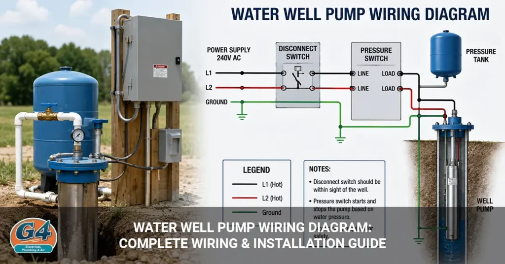
A water well pump wiring system connects the electrical supply to the pump through the appropriate breaker, pressure controls, and, on some systems, a separate control box. The exact wiring depends on the pump type, motor voltage, horsepower, and whether the pump uses a two-wire or three-wire motor.
A typical system may include a circuit breaker, pressure switch, control box, well pump, pressure tank, and grounding system.
Because well pumps can use hazardous electrical voltage and operate in wet environments, use the manufacturer’s wiring diagram for the exact pump model. Have a qualified electrician or well-pump professional handle electrical connections, testing, and repairs.
Water Well Pump Wiring Diagram
A typical well-pump wiring system routes power from the electrical panel through the appropriate controls before it reaches the pump motor. Understanding basic electrical wiring diagrams can also help explain how different components connect within a circuit.
A simplified system looks like this:
Electrical Panel
│
▼
Circuit Breaker
│
▼
Pressure Switch
│
▼
Control Box
(if required)
│
▼
Well Pump
The pressure tank works alongside the pressure switch to maintain water pressure in the plumbing system.
Not every well pump uses a separate control box. The pump’s motor design determines the correct arrangement.
How Does Well Pump Wiring Work?
Well-pump wiring allows the pump to start when water pressure drops and stop when the system reaches its pressure setting.
The basic sequence works like this:
- You use water in the home.
- System pressure falls.
- The pressure switch responds to the lower pressure.
- The control system calls for the pump to run.
- The pump moves water into the pressure system.
- Pressure rises.
- The pressure switch stops the pump.
The electrical wiring provides power to the motor, while the pressure-control system determines when the pump operates.
A wiring problem can prevent the pump from starting, cause repeated breaker trips, or create other electrical faults.
Well Pump Wiring Components
The main components include the pump motor, circuit breaker, pressure switch, wiring, grounding system, and sometimes a separate control box.
Well Pump Motor
The pump motor provides the mechanical power needed to move water from the well into the home’s water system.
A submersible pump places the motor and pump assembly down in the well.
A jet pump keeps the pump and motor above ground.
These two designs use different electrical and plumbing arrangements.
Circuit Breaker
The circuit breaker protects the electrical circuit supplying the well pump from excessive current.
The breaker must match the equipment, conductors, and applicable electrical requirements.
A breaker should never be replaced with a larger one simply because the existing breaker trips.
Repeated breaker trips need diagnosis.
Pressure Switch
The pressure switch starts and stops the pump based on changes in water-system pressure.
It works with the pressure tank to maintain the home’s water pressure.
Common pressure settings use a lower cut-in pressure and a higher cut-out pressure.
The exact settings depend on the well system.
Control Box
Some three-wire submersible pumps use a separate control box containing motor-starting components.
The control box may contain components such as:
- Start relay
- Capacitor
- Motor-control components
- Connections for the pump conductors
The control box must match the pump motor and manufacturer specifications.
Pressure Tank
The pressure tank stores pressurized water and helps reduce how frequently the pump starts.
The tank is part of the water-pressure system rather than simply another electrical component.
A problem with the pressure tank can cause rapid pump cycling even when the pump wiring works correctly.
2-Wire vs. 3-Wire Well Pump Wiring
Two-wire and three-wire submersible pumps use different motor arrangements, so their wiring diagrams are not interchangeable.
The names refer to the pump’s motor conductors and don’t simply mean that one system has one more ordinary wire than the other.
2-Wire Well Pump
A two-wire submersible pump typically contains its motor-start components within the pump assembly instead of using a separate above-ground control box.
This can make the above-ground electrical arrangement simpler.
The system still requires the correct power supply, grounding, protection, and pump-specific wiring.
Always use the wiring diagram supplied for the exact pump.
3-Wire Well Pump
A three-wire submersible pump typically uses a separate control box to manage motor-starting components.
The system commonly has:
- Electrical supply
- Pressure control
- Control box
- Pump conductors
- Grounding conductor
The control box must match the motor.
Using the wrong control box can cause improper operation or motor damage.
120V vs. 240V Well Pump Wiring
A well pump can use different supply voltages depending on the motor, and you must match the electrical supply to the pump’s specifications.
| Feature | 120V System | 240V System |
| Supply voltage | Lower | Higher |
| Typical use | Depends on equipment | Common for many larger pump systems |
| Wiring | Equipment-specific | Equipment-specific |
| Protection | Must match system | Must match system |
Never determine the required voltage from the pump’s appearance.
Check the motor nameplate and manufacturer’s documentation.
Electrical work involving these voltages should be performed by a qualified professional.
Well Pump Wiring Diagram by Pump Type
The wiring arrangement depends on whether the system uses a submersible pump, jet pump, or another pump design.
Submersible Well Pump Wiring
A submersible pump uses a motor and pump assembly installed down in the well and connects to the above-ground electrical control system through appropriately rated conductors.
A simplified system looks like:
Electrical Supply
│
▼
Pressure Control
│
▼
Control System
│
▼
Well Cable
│
▼
Submersible Pump
The exact conductor arrangement depends on whether the motor uses a two-wire or three-wire configuration.
Jet Pump Wiring
A jet pump sits above ground and uses a different motor and control arrangement from a submersible pump.
The motor remains accessible near the pressure system rather than inside the well.
The electrical design still needs:
- Correct voltage
- Proper circuit protection
- Grounding
- Motor-compatible controls
- Appropriate wiring
Use the pump manufacturer’s diagram rather than assuming a jet pump uses the same arrangement as a submersible pump.
Well Pump Pressure Switch Wiring Diagram
The pressure switch controls pump operation by responding to changes in water pressure.
A simplified system relationship is:
Electrical Supply
│
▼
Pressure Switch
│
▼
Pump / Control Box
The pressure switch typically has two important pressure points:
- Cut-in: The pressure level at which the pump starts.
- Cut-out: The pressure level at which the pump stops.
For example, a system may use a 40/60 pressure setting, but the correct settings depend on the specific installation.
If the pressure switch has burned contacts, mechanical damage, or other faults, the pump may fail to start or may operate incorrectly.
Because the switch contains electrical connections, have a qualified professional handle electrical testing and replacement.
Well Pump Control Box Wiring Diagram
A three-wire submersible pump may use a control box between the power supply and pump to manage the motor’s starting components.
A simplified layout is:
Electrical Supply
│
▼
Pressure Control
│
▼
Control Box
│
▼
Submersible Pump
The control box can contain components that help the motor start and operate correctly.
The box must match the pump motor.
Do not substitute a control box based only on voltage or horsepower. Motor-specific requirements matter.
How to Identify Well Pump Wires
The safest way to identify well-pump wires is to use the pump and control-box documentation instead of relying only on wire color.
Wire colors can vary between equipment and installations.
Before any electrical work, a qualified professional should verify:
- Pump model
- Motor voltage
- Motor type
- Manufacturer wiring diagram
- Conductor identification
- Grounding requirements
- Control-box compatibility
Never assume that a wire is safe because the pressure switch is off.
The circuit must be properly isolated and verified before qualified electrical work begins.
Well Pump Wire Size
The correct well-pump wire size depends on motor horsepower, voltage, current, wire length, temperature, installation conditions, and applicable electrical requirements.
Important factors include:
- Motor current
- Starting characteristics
- Voltage
- Distance from the electrical panel
- Voltage drop
- Conductor material
- Installation environment
- Applicable electrical code
A longer wire run can create greater voltage drop.
That’s why you shouldn’t choose a wire size based only on the pump’s horsepower.
The pump manufacturer may provide conductor-sizing information for specific models and installation conditions.
Well Pump Breaker Size
The correct breaker size depends on the pump motor, conductor requirements, starting characteristics, manufacturer specifications, and applicable electrical code.
A pump’s horsepower alone doesn’t provide enough information to select a breaker safely.
The electrical design needs to account for the motor’s operating and starting characteristics.
If your pump repeatedly trips its breaker, don’t simply install a larger breaker.
A repeated trip can indicate:
- Motor problems
- Damaged wiring
- Electrical faults
- Control-box problems
- Mechanical issues
Have the system diagnosed by a qualified professional.
Common Well Pump Wiring Problems
Common well-pump electrical problems include tripped breakers, failed pressure switches, damaged wiring, control-box faults, and pump-motor problems.
Pump Trips the Breaker
A breaker that repeatedly trips can indicate an electrical fault, damaged wiring, motor trouble, or another system problem. If the breaker itself appears faulty, circuit breaker repair may be necessary.
Don’t repeatedly reset the breaker.
If it trips again, have the circuit inspected.
Pump Runs Continuously
A continuously running pump can result from low pressure, a plumbing leak, pressure-control problems, insufficient water supply, or pump-system faults.
Check for obvious plumbing problems and unusual pressure behavior.
If the pump continues running when it should stop, professional diagnosis may be necessary.
Pump Doesn’t Turn On
A pump that doesn’t start can have a power, pressure-switch, control-box, wiring, or motor problem.
A homeowner can check whether the home’s power is on and whether a breaker has tripped.
Electrical testing beyond basic external checks should be left to a qualified professional.
Pump Starts and Stops Rapidly
Rapid pump cycling can indicate a pressure-tank problem, pressure-control issue, or another water-system fault.
Frequent starts place additional stress on the pump motor.
If cycling continues, have the pressure system inspected.
Low Water Pressure
Low water pressure doesn’t always indicate a wiring problem because plumbing restrictions, pump performance, pressure controls, and well conditions can also cause it. Other water pressure issues can also affect how the home’s plumbing system performs.
Check the pressure gauge if your system has one.
If pressure remains low, a well-pump professional can determine whether the cause comes from the pump, controls, plumbing, or water supply.
How to Troubleshoot a Well Pump That Won’t Run
You can perform a few basic external checks, but electrical testing and wiring repairs should be handled by a qualified professional.
Safe checks include:
- Check whether power is available in the home.
- Look for a tripped pump breaker.
- Check the pressure gauge.
- Look for visible plumbing leaks.
- Look for obvious damage around accessible equipment.
- Listen for unusual pump or control-system behavior.
Don’t:
- Open a control box.
- Touch exposed electrical conductors.
- Bypass a pressure switch.
- Replace a breaker with a larger one.
- Test energized wiring without proper training and equipment.
- Attempt to repair underground pump wiring yourself.
If the pump still won’t operate, professional diagnosis is the safer option.
Well Pump Wiring Safety
Well-pump wiring requires careful electrical work because the system can combine hazardous voltage with water and damp conditions. These risks make basic electrical safety especially important when dealing with pump wiring.
Important safety considerations include:
- Use properly rated conductors.
- Follow the pump manufacturer’s wiring diagram.
- Use appropriate circuit protection.
- Maintain proper grounding and bonding.
- Protect wiring from moisture and physical damage.
- Follow applicable electrical codes.
- Properly isolate power before qualified service.
- Verify that power is actually off before electrical work.
Never bypass electrical protection simply to get the pump running.
A temporary wiring fix can create a serious shock or fire hazard.
When Should You Call an Electrician or Well Pump Professional?
Call a qualified electrician or well-pump professional when the problem involves electrical testing, wiring, control boxes, breakers, motor connections, or repeated electrical faults. Professional electrical wiring can help ensure the pump circuit is properly installed and protected.
Professional service is especially important when:
- The breaker repeatedly trips.
- The pump won’t start.
- The pump runs continuously.
- Wiring appears damaged.
- The control box shows signs of damage.
- You smell burning.
- You hear unusual electrical sounds.
- Underground wiring may be damaged.
- The pump requires voltage testing.
- A motor or control component may have failed.
An electrician can handle the electrical side of the system, while a well-pump professional can diagnose pump, pressure, and well-system problems. In some cases, both may be appropriate.
Frequently Asked Questions
How do you wire a well pump?
Well-pump wiring connects the electrical supply to the pump through the appropriate circuit protection and pressure-control system. The exact arrangement depends on the pump type, voltage, motor design, and manufacturer requirements.
What does a well pump wiring diagram show?
A well-pump wiring diagram shows how the electrical supply, controls, pump motor, grounding, and related components connect within the system.
The diagram for one pump should not automatically be used for another model.
What is the difference between 2-wire and 3-wire well pumps?
A two-wire submersible pump typically contains its motor-start components within the pump, while a three-wire pump commonly uses a separate control box.
The wiring and control arrangements therefore differ.
Does a well pump use 120V or 240V?
A well pump can use 120V, 240V, or another specified voltage depending on the motor and system design.
Always check the pump’s nameplate and manufacturer’s documentation.
What size wire does a well pump need?
Wire size depends on motor current, voltage, horsepower, cable length, voltage drop, installation conditions, and electrical requirements.
There is no universal wire size for every well pump.
What size breaker does a well pump need?
The breaker must match the pump’s electrical characteristics, conductor requirements, manufacturer specifications, and applicable electrical code.
Don’t select a breaker based only on horsepower.
What does a well pump pressure switch do?
A pressure switch starts and stops the pump as water-system pressure falls and rises.
It works with the pressure tank to maintain the system’s pressure range.
Does every well pump need a control box?
No, not every well pump uses a separate control box. Some submersible pumps use a two-wire design with motor-start components contained within the pump, while many three-wire systems use an external control box.
Why does my well pump keep tripping the breaker?
A repeatedly tripping breaker can indicate a motor fault, damaged wiring, control-box problem, or another electrical or mechanical issue.
Don’t repeatedly reset the breaker. Have the system professionally diagnosed.
Why won’t my well pump turn on?
A well pump may fail to start because of a power problem, pressure-switch fault, control-box issue, damaged wiring, or motor failure.
Basic external checks are reasonable, but electrical testing should be left to a qualified professional.
Why does my well pump run continuously?
A pump may run continuously because of low system pressure, a plumbing leak, pressure-control problems, insufficient well supply, or a pump-system fault.
If the pump doesn’t stop normally, have the system inspected.
Can a homeowner replace well-pump wiring?
Well-pump wiring is not a good DIY electrical project because it can involve hazardous voltage, wet conditions, and buried or submerged conductors.
Use the manufacturer’s documentation and have electrical wiring, testing, and repairs handled by a qualified professional.
Final Thought
Water well pump wiring varies according to the pump type, motor voltage, horsepower, wire length, and control system.
The most important differences to understand are:
- 2-wire vs. 3-wire pumps
- 120V vs. 240V systems
- Submersible vs. jet pumps
- Systems with vs. without separate control boxes
A wiring diagram can help you understand how the system works, but it shouldn’t replace the manufacturer’s instructions or professional electrical work.
If your well pump trips the breaker, won’t start, runs continuously, or shows signs of electrical damage, don’t bypass the controls or experiment with the wiring. Have a qualified electrician or well-pump professional diagnose the system safely.